Willamette Falls Flow Control Structure
Oregon City, Oregon
|
Portland General Electric owns and operates the 18 MW Sullivan Hydroelectric Plant at Willamette Falls Dam. As part of an on-going effort to improve fish passage on the Willamette River, PGE implemented major structural upgrades on the dam facilities. PGE retained Cornforth Consultants to complete subsurface explorations, foundation design, engineering during construction, and construction inspection for the new structures. Major features included a forebay training wall, an elevated flume, a man-made island, and two inflatable diversion dams at the head of Willamette Falls.
The Sullivan Plant was constructed on the left bank of the Willamette River in 1895. It is an aging structure located between a navigation lock and an operating paper mill. PGE committed to an ambitious plan to retrofit the facility to aid endangered fish runs. Cornforth Consultants completed a detailed review of existing documents to determine the size and location of existing structure foundations, abandoned structures, and the locations of underwater debris. Geologic mapping was performed in and around existing facilities to develop a model for the proposed structures. Over-water subsurface exploration and in situ testing programs were conducted to characterize foundation conditions and engineering properties. Laboratory testing on river sediment and rock core was conducted to develop shear strength parameters for designing deep foundations. Laboratory shear strength was used with rock structure data to utilize a rock mass design approach to foundation analyses. The new flume structure routes downstream-migrating fish around the power turbines to an outlet at the base of Willamette Falls. The elevated flume is supported by a system of vertical and battered rock-socketed drilled shafts. Key design considerations included bearing and uplift capacity of shafts as well as differential settlement between shaft bents. The forebay training wall is located in an area that could not be explored with borings due to power generation considerations. It was originally designed to be supported on rock foundations. After the forebay was dewatered, foundation excavation uncovered rock-filled timber cribs supporting the existing navigation lock and seepage flowing into the excavation threatened to undermine the navigation lock structure. A micropile foundation system was designed and constructed as an emergency change order to fit construction within the permitted in-water work period. The new diversion dams consist of inflatable bladders anchored to bedrock with micropiles. The bladders inflate during fish migration to direct fish runs downstream through less hazardous portions of the falls. A cellular cofferdam island was designed and constructed adjacent to the diversion dams to act as a laydown area for maintenance operations. Dewatering analysis indicated high seepage was expected under temporary cofferdams; therefore, foundation grouting was implemented to minimize seepage flows. Geotechnical data and design reports were prepared for the various phases of the project, along with construction documents and post-construction reports. |
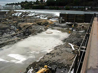
Willamette Falls Flow Control Structure Construction
Services Provided:
|